VG64
A second screen for the Commodore 64
ryan@hack.net / @hacknet - last updated 11-Jun-2021
Introduction
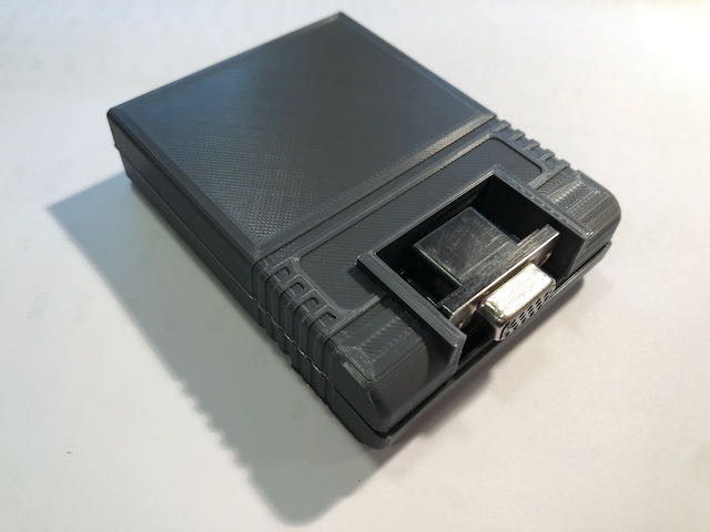
This was a quick hardware project to bring a second screen to the C64. The hardware fits into a standard size cartridge (with a cutout for the DE-15 connector) and outputs a VGA compatible 31kHz signal. It features 128K of static RAM for the framebuffer and a simple 1 bit per color DAC.
TL;DR
A framebuffer cartridge for the C64 with a VGA compatible output. Downloads here: GitHub
Software Interface
The cartridge can appear in any part of the 64k address space, including I/O1 or I/O2, and there's Verilog code to present either a window to the frame buffer @ EXROM, which costs 8k of BASIC memory, or a register-based approach which preserves RAM. The examples here use I/O1 at $DE00 for the control registers. You may wish to move these addresses to other locations if they conflict with some other add-on (second SID chip, etc.) There is support for a special token which must be written to avoid conflicts, but I don't have any extra hardware that causes problems.
The frame buffer is linear and not difficult to use like the native bitmapped C64 modes. It starts at $00000 in the static RAM.
Video output
Regardless of the selected mode, the cart outputs video at a 25MHz pixel rate. This is derived from the on-board 100MHz oscillator. This pixel rate is close enough to the standard 25.175MHz rate of a 640x480 @ 60Hz screen that every display device I've tried has no problem displaying the signal. Vertical & horizontal sync, and blanking areas are set for the correct polarity and length to trigger this mode.
Two interpretations of the frame buffer data are possible, a high resolution 640x480 1bpp mode and a lower resolution 320x480 multicolor mode. Both modes are palette direct.
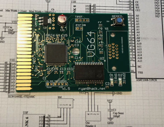
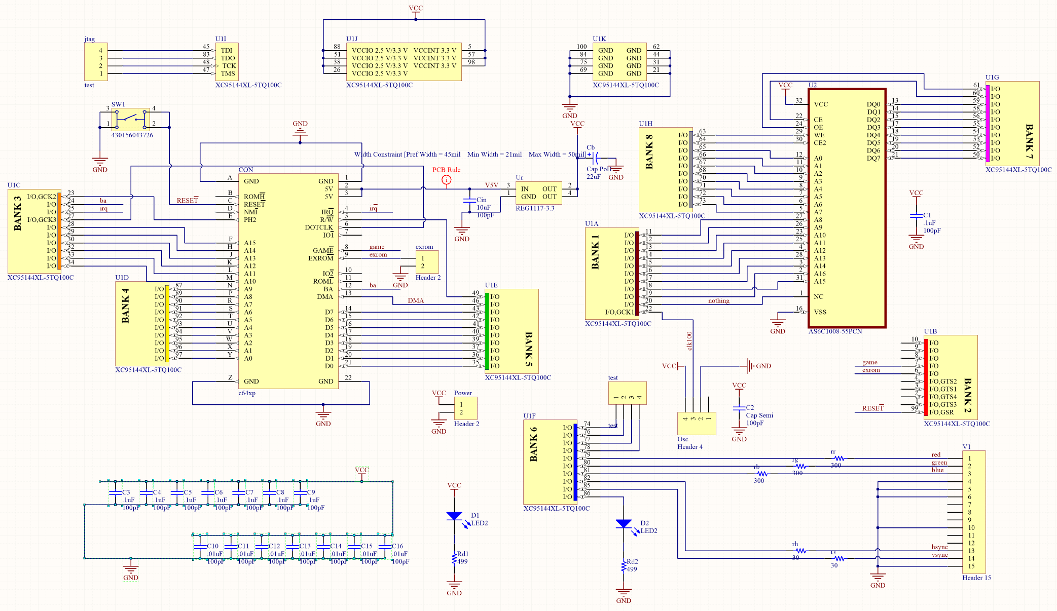
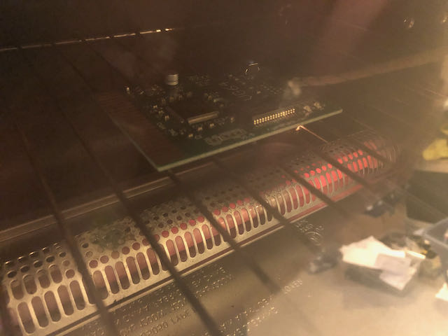
Hardware
The hardware is straightforward: 3.3V regulation, a CPLD, oscillator, and an SRAM. The SRAM spends half its time responding to the demands of the host, and half barfing out pixel data. The CPLD used here, a Xilinx 95144XL is 5V tolerant, so it happily exists on the C64 expansion bus, although it is powered by the 3.3V regulator along with the rest of hardware.
Almost all the macrocell resources of the CPLD are in use. I had hoped to fit a single hardware sprite for a pointer, but there's just not room.
For the 3d printing fans, STLs included for a C64 style cart enclosure with the required hole.
You will need a JTAG programmer to load the bitstream into the CPLD.
Note that this cart does not work on the Ultimate 64 replacement motherboard. From what I can tell the blocking issue is that the power-up sequence brings up logic signals prior to the 5V output. This may damage the cart. It would be quite cool to get this working as a 40MHz U64 could push a lot more pixels than a stock 1MHz C64. The cart does work fine with all the revisions of the C64, C128, and C64 Reloaded boards I had access to- it's a bit hard to say it's compatible with every version of the C64 or C128 that came out of Commodore- but the cart is well behaved IMHO.
BOM
4-layer PCB. Gerber files included. A bevel for the edge adds a lot to the cost, so just sand it by hand (don't skip this, you can destroy the female contacts).
Cart case top and bottom. STL files included.
22uF 6.6mm Aluminum polarized capacitor
Momentary switch, like pn 430156043726, if you'd like a reset button for your computer.
.1" header strips
0603 resistors: 2 499R, 3 300R, 2 30R
0603 capacitors: 10 0.1uF, 7 0.01uF
Generic 1117 3.3V Regulator
2 3.2x1.6 LEDs (helpful for debugging, but not required)
XC95144XL-5TQ100C CPLD (speed not important)
JEDEC 128kx8 SO Async SRAM a la AS6C1008-55PCN (don't go slower)
Right angle DE15 high density VGA through-hole female connector
Verilog
I'm not aware of an open toolchain for these CPLDs, but there are student editions available online which do compile and program these types of devices. I used Xilinx ISE 14.5. If someone finds an alternative to the 1st party toolchain for these chips, I'd love to hear about it.
Pixel packin'
In high resolution mode, each bit maps to one pixel. 1 = White, 0 = Black. Addresses move from (0,0) in the upper left most visible position to the lower right (639,479), by column then row. Bit 7 in each byte is the first pixel.
In multicolor mode, pixels are emitted at the same rate as monochrome mode, but each color channel has a different resolution. Green is 1/2x the pixel rate, while Red and Blue are 1/4x the pixel rate. The bit pattern to color channel mapping is per byte (chunky) and is:
G0 G1 G2 G3 R0 R1 B0 B1
While the on-screen representation of each framebuffer byte is the following:
Think "bayer pattern" but per line/per byte. There is no change to vertical resolution.
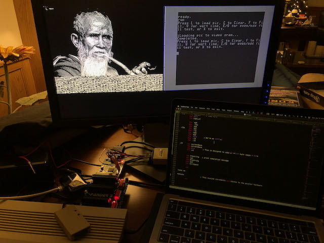
Converting images for display using ImageMagick, monochrome mode:
There's likely a way to use IM to pack the color channels, but I found it easier to just do it in python:
from PIL import Image
from array import *
import numpy as np

ir = Image.open("channel0.png")
ig = Image.open("channel1.png")
ib = Image.open("channel2.png")

ir = ir.resize((640,480))
ig = ig.resize((640,480))
ib = ib.resize((640,480))

r = ir.load()
g = ig.load()
b = ib.load()

arr=np.zeros((480,80,8))
out=np.zeros((480,640))

for y in range(0,480):
        for x in range(0,80):

                # 0 1 2 3 is green level
                # 4 5 is red level
                # 6 7 is blue level

                # GREEN

                arr[y][x][0]=(g[x*8+0,y]+g[x*8+1,y])/2
                arr[y][x][1]=(g[x*8+2,y]+g[x*8+3,y])/2
                arr[y][x][2]=(g[x*8+4,y]+g[x*8+5,y])/2
                arr[y][x][3]=(g[x*8+6,y]+g[x*8+7,y])/2

                # RED

                arr[y][x][4]=(r[x*8+0,y]+r[x*8+1,y]+r[x*8+2,y]+r[x*8+3,y])/4
                arr[y][x][5]=(r[x*8+4,y]+r[x*8+5,y]+r[x*8+6,y]+r[x*8+7,y])/4

                #BLUE

                arr[y][x][6]=(b[x*8+0,y]+b[x*8+1,y]+b[x*8+2,y]+b[x*8+3,y])/4
                arr[y][x][7]=(b[x*8+4,y]+b[x*8+5,y]+b[x*8+6,y]+b[x*8+7,y])/4

for y in range(0,480):
        for x in range(0,80):
                for bit in range(0,8):

                        arr[y][x][bit] = int(round(round(arr[y][x][bit])/255))

newfile=open("output.bin","wb")

for y in range(0,480):
        for x in range(0,80):

                out[y][x] = int(arr[y][x][0] + arr[y][x][1]*2 + arr[y][x][2]*4 + arr[y][x][3]*8
+ arr[y][x][4]*16 + arr[y][x][5]*32 + arr[y][x][6]*64 + arr[y][x][7]*128)

                newfile.write(out[y][x].astype(np.ubyte))

newfile.close()
You should be left with a 38,400 byte file for either mono or multicolor mode.
Had I used a '288 device, I could have probably jammed a hardware sprite into the CPLD, but that has a bigger footprint and cost, and I have a lot of '144s laying around, so, yeah, I used one and it's good enough. This sort of thing continues to make you appreciate what the original designers could do in just a few thousand transistors.
The 128k of RAM on the card could really be used for all sorts of things, including RAM expansion (via banking), a RAM disk, etc. There's nothing in the hardware preventing this from happening.
Could this be refactored to add double/tripled buffering, scroll registers, or a mid-vscan mode change? Blink? Certainly a "start pointer here" register.
Add a chargen ROM and change to a text/character mode?
Palette indirect modes?
I did write verilog to auto-inc the framebuffer pointer, but it ended up using a lot of the cpld resources- probably for the big/wide adder required. This should be revisited.
I need to write more interesting demos for this.
I wouldn't recommend building one of these carts, as it was a personal project to revisit OG video and retro-computing and it's only going to be useful for software written to use this hardware. Plus, it may set your house on fire and say mean things about your mother.
; Multicolor mode demo for VG64
; r. brooks
; New Version 1/19/2021 - for reg scheme
; Assumes token register at $DE00, EXROM high, and NO banking at $8000
; Multicolor Demo and test code
!to "mc2test.o", cbm
; BASIC stub to get a tokenized SYS command in. Grabbed from
; https://harald.ist.org/howto/c64/acme-asm-template.html
*= $0801 ; Load point $0801 (BASIC START)
_FSTART ; This binary must begin with the bytes
; representing the BASIC program: 0 SYS2061
BASIC_program
!byte $0b,$08 ; $0801 Pointer to next line
!byte $00,$00 ; $0803 Line number (0)
!byte $9e ; $0805 SYS
!byte 48+(entry_point/1000)%10 ; Decimal address of program entry point
!byte 48+(entry_point/100)%10
!byte 48+(entry_point/10)%10
!byte 48+(entry_point/1)%10
!byte $00 ; $080a End of BASIC line
!byte $00,$00 ; $080b End of BASIC program
entry_point ;JMP boot ; $080d First byte after the BASIC program
;; defines
chrout = $ffd2
chrin = $ffcf
autotoken = $C0 ;Multicolor mode, screen on
token = $de00 ; vg64 registers
lsb = $de01
msb = $de02
operand = $de03
zp1 = $fd ; available zero page addrs
zp2 = $fe ; pointer to source
zpA = $fb ; framebuffer pointed in zp
zpB = $fc
;; program
!zone main
boot cld
lda #23
sta $d018 ; Switch to lower case
lda #